
Imagine this: you’re in the heart of the countryside, surrounded by the peace of the great outdoors, but your trusty lawnmower suddenly sputters to a halt. As you peer into the engine, a jumble of wires and components stare back, leaving you feeling lost and bewildered. Don’t fret, fellow enthusiast! This is where understanding the Briggs & Stratton magneto wiring diagram comes in. This seemingly cryptic chart holds the key to unlocking your engine’s ignition system, paving the way for a smooth and efficient mowing experience.

Image: schematron.org
The Briggs & Stratton magneto wiring diagram is essentially the blueprint for your engine’s ignition system, a vital component that generates sparks to ignite the fuel-air mixture, bringing your engine to life. This diagram provides valuable insight into how the different components – the magneto, wiring, and ignition coil – interact, allowing you to troubleshoot and repair problems with confidence.
Deciphering the Code: Fundamentals of Ignition Systems
Before delving into the intricate details of the wiring diagram, let’s lay a solid foundation. Briggs & Stratton engines, particularly those powering lawnmowers and small engines, typically employ magneto ignition systems. This system utilizes a rotating magnet to generate electricity, which in turn energizes the spark plug to ignite the fuel.
The core elements of this system are:
- The Magneto: This device, resembling a small electric motor, houses permanent magnets that rotate to produce a magnetic field.
- The Ignition Coil: This component serves as a transformer, converting the low-voltage electricity generated by the magneto into a high-voltage spark that’s strong enough to ignite the fuel.
- The Spark Plug: This ceramic-coated metal component delivers the high-voltage spark to the fuel-air mixture within the combustion chamber.
- The Wiring: This network of wires connects the magneto, ignition coil, and spark plug, ensuring smooth transmission of electricity.
Navigating the Diagram: A Detailed Exploration
Now, let’s dive into the heart of the matter: the Briggs & Stratton magneto wiring diagram. This diagram, often printed on a sticker or label, is essential for understanding how electricity flows within the ignition system. Here’s a breakdown of its key features:
- Component Labeling: Each component in the system – magneto, ignition coil, and spark plug – is clearly labeled on the diagram.
- Wiring Pathways: The diagram visually depicts the path of each wire, showing connections to each component.
- Color Coding: Different colors are assigned to each wire, making it easier to trace their paths.
- Reference Points: The diagram may include reference points, such as terminal numbers or lettered markings, to further clarify wiring connections.
- Diagram Types: Briggs & Stratton provides various types of magneto wiring diagrams, tailored to specific models and engine variations.
Decoding the Language of Wires: Common Color Codes and Connector Types
Understanding the color codes used in Briggs & Stratton wiring diagrams is a crucial step in properly interpreting them. Typically, wires are color-coded to represent their functions.
- Black: Power or Ground
- Red: Ignition Circuit
- Blue: Magneto Output
- Yellow: Coil Output
- Green: Ground
- White: Spark Plug
- Orange: Alternator
Connectors can also vary in type, so familiarity with common ones is essential.
- Male/Female: These connectors are often used in various parts of the ignition system.
- Terminal Connectors: These connectors are typically used at the spark plug and magneto terminals.
- Blade Connectors: These connectors are often used for high-voltage connections at the spark plug.
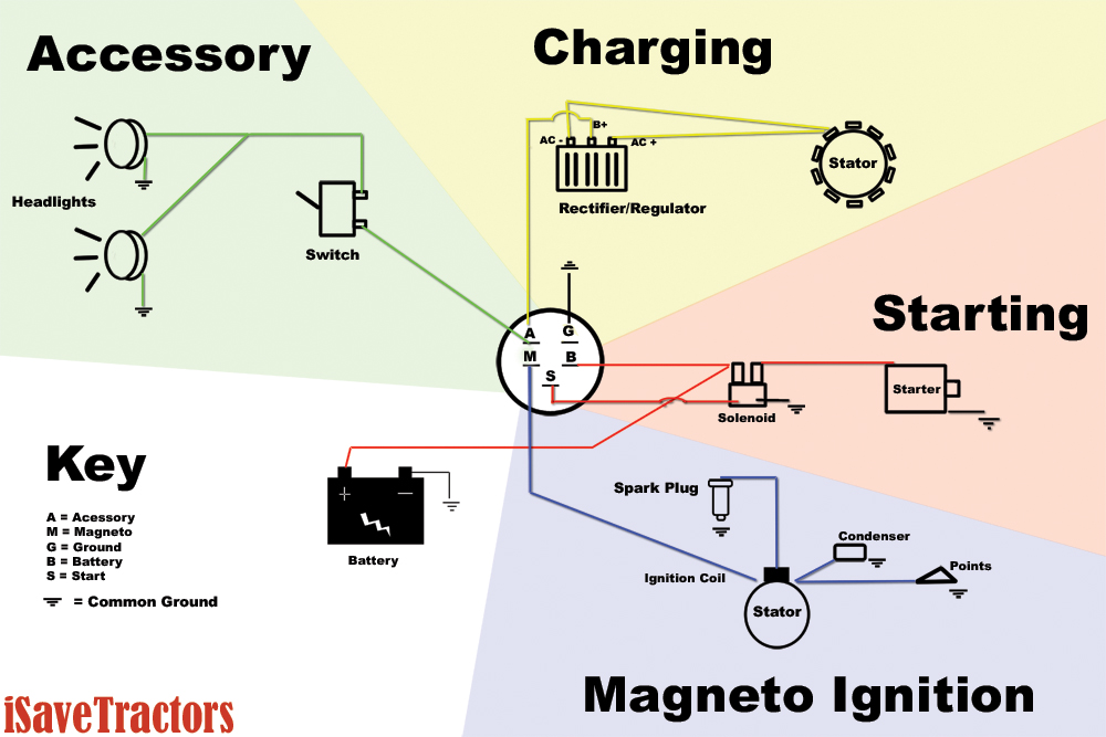
Image: switchwiringdiagrams.blogspot.com
Troubleshooting like a Pro: Utilizing the Diagram for Repairs
The Briggs & Stratton magneto wiring diagram becomes a valuable tool when troubleshooting ignition problems. By carefully examining the diagram, you can:
- Diagnose Wiring Issues: Trace the path of each wire to ensure connections are secure and properly connected.
- Identify Broken Wires: Inspect the wires for signs of wear, breaks, or corrosion.
- Test Component Functionality: By using a multimeter, you can test the flow of electricity through the magneto, ignition coil, and spark plug; confirming the integrity of the circuit.
- Locate Problematic Components: The diagram will help you pinpoint the faulty component responsible for ignition issues.
Mastering the Art of Maintenance: Keeping Your Ignition System Running Strong
Just like any crucial system, regular maintenance is key to keeping your Briggs & Stratton engine’s ignition system running smoothly. Here are some tips:
- Inspect and Clean Wires: Periodically check the wires for wear, corrosion, or loose connections. Clean any dirt or debris for optimal conductivity.
- Replace Worn Wires: Replace damaged or frayed wires promptly to prevent them from causing short circuits or interruptions.
- Inspect Spark Plugs: Check for wear and fouling on the spark plug electrodes. Replace them according to manufacturer recommendations.
- Inspect Magneto Components: Ensure the magneto and ignition coil are properly secured and free of any damage.
- Use High-Quality Parts: When replacing components, use only genuine Briggs & Stratton parts designed for your engine.
Unveiling the Secrets: Expert Insights and Actionable Tips
When tackling ignition system issues, seeking guidance from experienced technicians is always a wise move. Here are some tips they often emphasize:
- Safety First: Always disconnect the spark plug wire before working on any components to prevent accidental injury.
- Use a Digital Multimeter: This tool allows you to accurately measure voltage, current, and resistance, aiding in accurate diagnosis.
- Consult the Owner’s Manual: Your engine’s owner’s manual contains specific instructions, diagrams, and troubleshooting guides tailored to your model.
Briggs And Stratton Magneto Wiring Diagram
Conclusion: Mastering the Magneto Wiring Diagram for Success
By understanding the intricacies of the Briggs & Stratton magneto wiring diagram, you’ll gain a deeper appreciation for your engine’s ignition system. This knowledge will equip you to confidently troubleshoot problems, perform basic maintenance, and keep your lawnmower running smoothly for years to come. Don’t let a mysterious jumble of wires intimidate you! Embrace the challenge, grasp the concepts, and experience the satisfaction of a perfectly running engine. So, roll up your sleeves, grab your multimeter, and delve into the fantastic world of magneto wiring!


